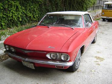
I have started working on a replacement engine for my 1965 Monza Convertible. This will be based on mods I think the average guy would be willing to do, ie; modify the heads to accept fuel injection using a dual plenum system and single throttle body but use the basic short block many of you guys have already built. This is really an exercise at trying to develop a setup the average guy could install by basically swapping the cylinder heads, adding a few sensors and fitting a stand alone EFI unit. At this time I am exploring the design ideas I have been thinking about.
I have most of the basic engine specs I think will work. But where I will depart from the norm is in spending more time testing the specs of the components in my engine software program to see if I am helping engine efficiency.
The engine starts out as a 110 based smog unit. Stock crank and rods, pop-up smog pistons. I will run my .040" OS TRW pistons and a custom ground hydraulic cam. The heads I will use will be my 110 big valve conversion heads ( I already have a pair that I need to use). These heads started life as 95hp units. I have added an extra carb mounting pad to each head just like the 140 heads have. I'll post pics as this comes together.
I am finishing the adapter manifolds that will fit the 40MM Webers onto these heads. The extra carb pad is in the same position as on the 140 heads so the manifolds will fit the 140's also. The heads will get my big valve conversion and chamber welding, flycutting to raise the compression to 9.5:1, 1 3/8" angle port exhaust and angled spark plugs. I'll run these in my 65 Vert and spend some time on the chassis dyno setting the jets and timing for best run.
The adapter manifolds will be welded together this coming weekend (weather permitting).
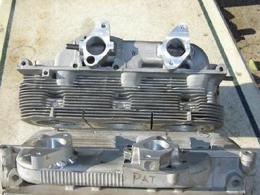
Notice on the pic at left the new carb adapters being fit to the intake manifolds. The tubes are already welded and the mounting pads are ready for welding. Then the final machining to make them flat and level with the stock carb pad. Also note the tube has a slightly larger ID. The stock pad will be opened up to match.
Since the new carb pads are being mounted in the same position as on 140 heads these 95 heads will allow both my 2BBL Weber manifold adapters and original 140 carbs to be used.
02.07.2011
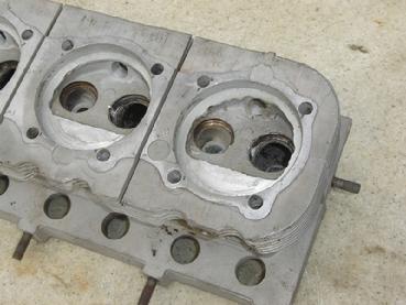
At left you will see the 95 heads with the finished extra carb mounting pad. The original mounting pad has been opened up to 1.375", the same as the added pad. I still need to weld up the combustion chambers, plug and weld the spark plug holes and machine for the new 3/4" reach plugs. After that I need to clean up the guide bores, make and install the guides and cut and install the larger valve seats. Finished...right.
Here is a picture of the 95 head during the upgrades. The seats have been removed and spark plug holes milled out. I still need to fill in the plug holes so I can change the angle. And the chambers have an abrupt step from the quench to the chamber proper. I'll weld this step so I can machine it to a more gradual shape.
03.27.2011
I finally got around to making the spark plug hole plugs for the 95 heads. Each one has a .002" interference fit so they need to be chilled for installation. But my nitrogen bottle is bad and will only keep the nitrogen for part of a day. At $40 per 20 liters I am tired of wasting money. So I ordered a new bottle and once it arrives I'll install these plugs and finish the chamber welding. Then just some clean up with the die grinder, drill and tap for the angle plugs and final machining and these heads will be ready.
06.05.2011
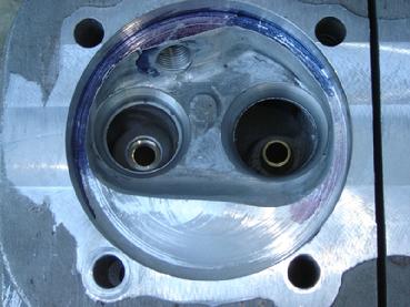
Finally got back to the 95 heads for the Vert. I machined the chamber area I welded for the angle plug. This creates the flat surface perpendicular to the spark plug. Next I need to mark and spot face the plug's working end position on this flat surface, transfer the same to the other chambers and, from the opposite side cut the plug hole and spot face for the 3/4" reach. Finish off by cutting the threads.
This is the modified 95 chamber ready for a final sanding. Doesn't look anything like a 95 chamber. Nor a 110 or 140 chamber either.
I decided to run a different plug angle than on the race heads. I think this will help the intake CFM. I feel the intake charge flows quite a bit more around the short side radius instead of skipping across the valve opening toward the quench. I need to check this idea on the race heads to be sure. If this is true then this latest angle plug will be the best as it will not protrude like a bump into the chamber but will be a smooth, gentle surface that will allow the charge to enter and swirl into the chamber. After I sand these chambers I'll cut the valve job, blend the intake ports and work on the exhaust ports a bit. The exhaust port exit area needs to be opened up to match the SS exhaust tubes I am using for the angle ports.
09.09.2011
Spark plug holes are cut and threaded. I need to clean up the chambers a bit then finish the valve job. And port the intakes somewhat. Just a little. Still waiting for the exhaust tubes to be bent. The man bending my stainless should have them ready next week. Then I can install them and finish the angle ports.
Once the heads are ready I'll pull the engine out of the Vert and tear it down. It has an engine number that says it is a 1967 smog motor. I am not sure if it is and don't know if it has smog pistons with the compression dome or flat top pistons. I'll assemble this with flat tops that will work with these heads. If the smog engine has pop-up pistons I'll flycut these into flat tops and use them if they spec out ok. I still want to change the cam to the Isky 280 I pulled out of a poorly assembled engine I bought. I have a set of stock rods with ARP bolts that are ready and a hard chromed crank also awaiting use.
09.17.2011
Intake work...
z 21.8 48.8 48.4 0s < MARK 0.10
14.8 96.2 95.5 0s < MARK 0.20
11.0 129.2 128.3 2s < MARK 0.30
10.2 138.1 137.1 4s < MARK 0.40
10.2 137.6 136.6 3s < MARK 0.50
10.2 138.0 137.0 3s < MARK 0.60
.000 .000 0.0 .001s ;Edit
95 2 carb head bare, no weber manifold;
.001 .004 0.0 .000s
z 22.4 48.7 48.4 0s < MARK 0.10
14.6 96.6 95.9 0s < MARK 0.20
10.7 130.3 129.4 0s < MARK 0.30
10.0 138.5 137.5 0s < MARK 0.40
10.1 138.7 137.7 0s < MARK 0.50
10.1 138.0 137.0 0s < MARK 0.60
.002 .001 0.0 .000s ;Edit
95 2 carb head w/ weber manifold only;
.002 .001 0.0 .000s
z 21.3 50.7 50.4 2s < MARK 0.10 14.1 96.4 95.7 2s < MARK 0.20 10.8 127.6 126.6 0s < MARK 0.30 10.1 136.1 135.2 0s < MARK 0.40 10.3 134.6 133.6 3s < MARK 0.50 10.4 135.2 134.3 3s < MARK 0.60 .059 .001 0.0 .000s ;Edit
95 2 carb head w/ manifold and weber;
.001 .002 0.0 .001s
Exhaust work...
z
13.1 23.5 23.3 0s < MARK 0.10
9.31 56.4 56.0 0s < MARK 0.20
7.40 78.2 77.6 3s < MARK 0.30
6.78 86.7 86.1 2s < MARK 0.40
6.45 90.4 89.8 0s < MARK 0.50
6.31 93.2 92.5 4s < MARK 0.60
.001 .000 0.0 .001s ;Edit no clay in exh;
.000 .004 0.0 .001s
z
13.0 21.3 21.1 0s < MARK 0.10
9.57 55.9 55.5 0s < MARK 0.20
7.84 74.3 73.8 0s < MARK 0.30
7.27 81.4 80.8 3s < MARK 0.40
7.04 84.6 84.0 4s < MARK 0.50
6.90 86.7 86.1 3s < MARK 0.60
.031 .001 0.0 .001s ;Edit
95 2 carb exh w/ clay for psudo d port;
.000 .000 0.0 .001s
z
13.1 21.9 21.7 0s < MARK 0.10
9.53 53.6 53.2 4s < MARK 0.20
7.94 72.6 72.1 4s < MARK 0.30
7.38 79.4 78.8 4s < MARK 0.40
7.09 82.5 81.9 3s < MARK 0.50
6.92 84.4 83.7 3s < MARK 0.60
.001 .001 0.0 .004s ;Edit
95 2 carb exh w/ bigger d port;
.002 .002 0.0 .002s
z
12.7 22.7 22.5 0s < MARK 0.10
9.31 57.2 56.8 0s < MARK 0.20
7.38 79.8 79.3 0s < MARK 0.30
6.74 88.1 87.4 0s < MARK 0.40
6.42 93.0 92.3 0s < MARK 0.50
6.26 94.2 93.5 0s < MARK 0.60
.001 .001 0.0 .003s ;Edit
95 2 carb w/ small d port removed;
.001 .001 0.0 .003
The 95 heads are all but finished. I still need to fit the angle ports and weld on the header flanges. The tubes are finished but I am waiting for the flanges to arrive. So I decided to check the heads on the flow bench. I checked the intake bare, with the Weber manifold attached and then with the 40 IDF Weber attached to the manifold. Here is the data: (remember the 3rd column is the CFM)
Looks like I need to comment... The port doesn't want to flow beyond the .400" valve lift. Probably due to the entire factory design w/ the plenum, 90 deg turns, etc. Thats OK because I won't be lifting the valve over .400" anyway. So I'm not working any harder on the flow.
On the exhaust I tried something. I have been thinking about the abrupt turn out from the chamber to the port and out and how on some engines adding a step at the SSR side of the exit (read "D" port) causes the CFM to increase. So I left material in this area and checked the flow... 1st test. Then I added a bit of clay to build this material up a bit. CFM dropped... 2nd test. I added a bit more and again the CFM went down... 3rd test. So, I decided to remove the clay and grind out the material to create a nice round port that blends with the SS tube. The 4th test shows the CFM increase over all previous tests. So... on this head a "D" port exhaust will hurt the flow. I'll check this on the race heads to confirm.
Also note the ratio of exhaust flow to intake. 65% exhaust to intake is not really bad considering how poorly the exhaust flows on a Corvair head. I did work a lot more on the exhaust ports than on the intakes. I think there is a little more CFM available with more exhaust work but overall I am quite satisfied with these results. This should be a sweet running engine.
10.08.2011
Ok, I rechecked the OT-20 specs and I see I Will be opening the intake valves over .400". More likely .470" with the 1.6:1 rockers. So I do need to find a bit more flow. Otherwise the intakes will be choked and will limit the top RPM. So I will spend a bit more time; probably around the guide boss. I'll post the results soon.
10.09.2011
.008 .003 0.0 .006s
z
20.9 52.1 51.7 0s  < MARK 0.10
14.0 98.5 97.8 0s  < MARK 0.20
10.5 131.8 130.8 0s  < MARK 0.30
 9.79 140.7 139.7 3s < MARK 0.40
9.88 141.1 140.1 3s  < MARK 0.50
10.0 139.4 138.4 3s  < MARK 0.60
.002 .003 0.0 .001s;Edit
slight tapering at guide boss;

.008 .006 0.0 .007s
z
21.5 51.5 51.2 0s  < MARK 0.10
14.5 98.1 97.4 1s  < MARK 0.20
10.7 130.9 129.9 0s  < MARK 0.30
9.91 140.7 139.7 0s  < MARK 0.40
10.1 141.1 140.0 0s  < MARK 0.50
10.2 139.9 138.9 0s < MARK 0.60
.014 .003 0.0 .000s;Edit
more tapering at guide boss;

.007 .008 0.0 .007s
z
22.6 51.5 51.2 0s  < MARK 0.10
14.5 97.9 97.2 0s  < MARK 0.20
10.8 131.5 130.6 0s  < MARK 0.30
10.00 140.9 139.8 0s  < MARK 0.40
10.2 139.1 138.1 0s  < MARK 0.50
10.1 139.1 138.0 0s  < MARK 0.60
.003 .003 0.0 .004s;Edit
open port entrance at roof;
.004 .011 0.0 .000s S
.008 .003 0.0 .006s
z
22.2 54.0 53.6 0s  < MARK 0.10
13.5 106.6 105.8 0s  < MARK 0.20
10.5 134.8 133.9 0s  < MARK 0.30
9.90 142.0 140.9 0s  < MARK 0.40
10.1 140.2 139.1 3s  < MARK 0.50
10.1 139.7 138.7 1s  < MARK 0.60
.002 .002 0.0 .001s;Edit
add 30 deg back cut to valve;

.004 .002 0.0 .002s
z
22.1 55.3 54.9 1s  < MARK 0.10
13.6 107.1 106.3 4s  < MARK 0.20
10.6 135.4 134.4 0s  < MARK 0.30
10.1 141.5 140.5 0s  < MARK 0.40
10.2 141.0 140.0 3s  < MARK 0.50
10.2 140.2 139.2 0s  < MARK 0.60
.026 .001 0.0 .000s;Edit
swirl polish intake valve;

.001 .000 0.0 .003s
z
21.8 55.2 54.8 0s  < MARK 0.10
14.0 105.8 105.0 0s  < MARK 0.20
11.0 131.7 130.7 3s  < MARK 0.30
10.5 138.0 137.0 0s  < MARK 0.40
10.6 136.4 135.4 0s  < MARK 0.50
.001 .000 0.0 .000s;Edit
w/ weber and adapter manifold;
.003 .000 0.0 .001s
I spent a little time (2 hours) trying to get a bit more CFM on the intakes. This is time spent on only 1 intake for now. I cut around the guide boss 2 times and the CFM went up a bit but then no more. Next I cut a little at the port entrance but the flow went down slightly at the .500" lift. I'll stay away from here on these heads. I had been thinking about making a small back cut so I tried this and the CFM went up a lot at the .200" lift - very nice. And finally I swirl polished the intake and did not see very much increase. Notice the intake flow above with the Weber and adapter at the .400" lift - 135.2 CFM. With the porting I did today the CFM only went up 1.8 CFM at .400" lift. I think the Weber is limiting the CFM. I have a Rochester carb adapter for my flow bench and will fit the Weber and see what it flows by itself. Then I'll know for sure.
So I think I am at the end on these ports. Now I just need to cut the remaining 5 and these heads will be finished.
I did look into the spark plug hole on the smog engine in the Vert and yes, this is a smog motor with the pop-up pistons. I need an adjustable piston vise so I can mill off the compression pop-up. An aluminum order needs to be placed for materials to make the vise. I have been thinking I'll make 2 vises and sell one. Anyone interested?
10.21.2011
.004 .004 0.0 .005s
z
12.8 27.1 26.9 0s  < MARK 0.10
9.27 59.9 59.5 0s  < MARK 0.20
7.23 83.2 82.6 0s  < MARK 0.30
6.66 92.2 91.5 0s  < MARK 0.40
6.36 96.6 95.9 0s  < MARK 0.50
6.24 100.3 99.6 0s  < MARK 0.60
.030 .005 0.0 .005s;Edit
test w/ stock 140 exh valve;
.001 .007 0.0 .001s
.000 .003 0.0 .001s
z
12.6 31.1 30.9 0s  < MARK 0.10
8.76 66.8 66.3 0s  < MARK 0.20
7.21 84.8 84.2 1s  < MARK 0.30
6.68 92.1 91.5 0s  < MARK 0.40
6.41 96.1 95.4 3s  < MARK 0.50
6.26 98.4 97.7 0s  < MARK 0.60
.001 .000 0.0 .000s;Edit
30 deg back cut on exh valve;
.003 .001 0.0 .002s
Here is a side by side comparison of the 1 3/8" angle port exhaust on the 95 Vert heads. The only difference is I made a 30 deg back cut on the exhaust valve and re-ran the test to check for any CFM increase. Notice the increases in the .100" to .300" lifts. A beneficial bump. But over .400" the flow drops off a bit. I'll try the swirl polish tomorrow. 6.8 CFM at .200" is a help.
10.24.2011
95 Vert intake:

22.2 54.0 53.6 0s  < MARK 0.10
13.5 106.6 105.8 0s  < MARK 0.20
10.5 134.8 133.9 0s  < MARK 0.30
9.90 142.0 140.9 0s  < MARK 0.40
10.1 140.2 139.1 3s  < MARK 0.50
10.1 139.7 138.7 1s  < MARK 0.60

add 30 deg back cut to valve;

95 Vert exhaust:

12.6 31.1 30.9 0s  < MARK 0.10
8.76 66.8 66.3 0s  < MARK 0.20
7.21 84.8 84.2 1s  < MARK 0.30
6.68 92.1 91.5 0s  < MARK 0.40
6.41 96.1 95.4 3s  < MARK 0.50
6.26 98.4 97.7 0s  < MARK 0.60


30 deg back cut on exh valve;
Stock 140 intake:
18.0 53.5 53.1 0s < MARK 0.10
11.5 94.1 93.4 0s < MARK 0.20
8.96 119.9 119.1 1s < MARK 0.30
7.51 138.0 137.0 2s < MARK 0.40
6.78 148.8 147.7 0s < MARK 0.50
6.50 152.9 151.8 0s < MARK 0.60
;Edit
bone stock 140 intake;
Stock 140 exhaust:
12.9 32.2 32.0 0s < MARK 0.10
10.0 59.3 58.9 0s < MARK 0.20
8.39 80.2 79.7 4s < MARK 0.30
7.66 90.3 89.6 6s < MARK 0.40
7.27 95.6 94.9 6s < MARK 0.50
7.11 98.0 97.3 7s < MARK 0.60
;Edit
bone stock 140 exh.;
Here is an interesting comparison. On the left is my modified 95 head and right is a stock 140 head. I hope you can see this lined up on your monitor as mine is. Again the CFM is column 3.
The 140 head intake flows better above .400" lift but that is as it should be since the intake valve is .200" larger. Not bad for a small valve head, right? Exhaust is very close to dead even and a bit better at .300" lift.
10.24.2011
Weber manifold adapter:
213.3 CFM
Weber sitting on adapter w/ velocity stack:
172.1 CFM w/ 28MM choke
181.8 CFM w/ 30MM choke
185.6 CFM w/ 32MM choke
So... finally some solid data. ;) Anyway, looks like the manifold alone will not hamper any CFM I can get on either the hot 95/110 heads or a 140 ported. With the Weber the CFM drops but is higher than I thought it would be. This Weber came with 28MM venturis. I acquired both the 30MM and 32MM venturis and rechecked the Weber. Tested through 1 barrel only. Same with the manifold adapter.
So on the built 95 engine and on a 140 engine the CFM for this 2bbl Weber is the total of both bores. The CFM per carb is double the number at the left. If I run the 28MM chokes then my total CFM available per carb is 344.2, or 688.4 for the engine. Which is more than enough.
I think the 40MM 3BBL Webers will flow the same given the same venturi. I'll see about finding someone with a 40 IDA 3C and a 46 IDA 3C for me to test.
Here is an interesting side note:
My race heads for the Hayabusa TB's are flowing 199.8 CFM at .600" so far (2 days of testing). If I was using 40MM Webers even with the 32MM chokes they would be restricting the total air this engine needs.
10.31.2011
The heads are nearly complete. The only thing left is to mill off the weld bead, dress the port openings with a die grinder where the excess weld is and send the heads off for the ceramic coating in the chambers, exhaust ports and valve faces.
I have an engine overhaul I am working on but as soon as this goes home I'll remove the engine from the Vert and tear it down for it's rebuild. And I ordered the custom cam today. This cam has been selected to work with the engines specs; bore, stroke, rod length, CR, head flow, etc. This should work great.
After I install the completed engine I'll need to fabricate the headers. But first I'll need to order the collectors and muffler then choose the pipe needed to connect everything. I really want to get this running for the spring.
12.12.2011
The heads are boxed up and ready to ship off for ceramic coating. The valve faces, combustion chambers and exhaust ports will be coated. After their return I need to finish off the intake ports and get them ready for pre-engine assembly. I'll be checking rocker arm geometry and setting the pushrod lengths.
01.08.2012
Ceramic is applied to the chambers, valve faces and exhaust ports
Ok, here they are. Polymer Dynamics, Inc. applied the ceramic coatings. They turned out great. These guys are highly recommended. Fast turn around too.
I need to finish off the intake ports with a little more flow work. Basically trying to equalize all the intakes. Then on to the trial engine assembly. I will be correcting the rocker arm geometry w/ custom length pushrods. I'll also check all clearances so final assembly will move smoothly.
01.25.2012
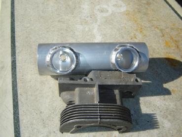
Plenum pieces before welding
Here is the start of my EFI design for the 4 carb "95" engine. I will build 2 plenums that will attach to the stock carb mounting pads. Velocity stacks are fit in the plenums with the injector bungs directly over each stack. Below the stack will be a tube that will have the mounting pad welded to the base. An equal sized tube will connect both plenums and have the throttle body mount near the center. Idle air control, map sensor and power brake fittings will be attached at the throttle body mount. I am designing this system to be usable on any 140 from mild to wild. That is with the original carb mounting pads. The only changes that might be necessary would be the throttle body size and ID of the adapter tubes that fit onto the heads. All other variables can be controlled via the EFI ECU. The injector's size need to be selected based on the HP expected.
This design would also lend itself to turbo use quite well. I am talking about a ground up re-design, not fitting this onto a turbo Corvair. I have another design that is better matched to the stock turbo set-up. That will come later.
01.30.2012
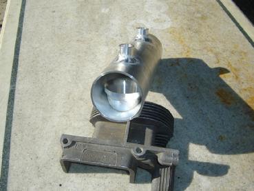
End view with velocity stack and injector bungs before end cap is welded on
Engine's view of plenum showing injector bung through velocity stack
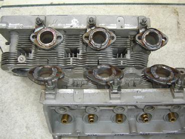
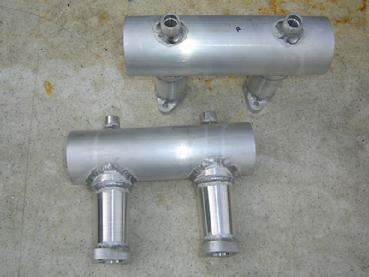
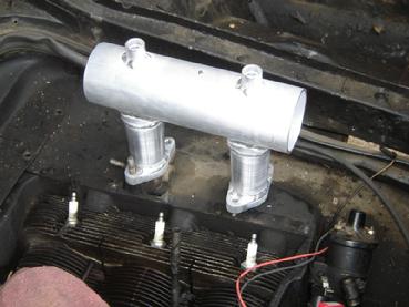
Side and top view of the manifolds
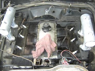
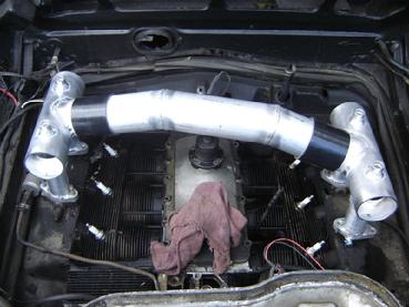
So, looking at the pics above doesn't really convey the design too well. Here are three pictures of the manifolds welded together. I also decided to set them on the smog heads that are still in the car. Maybe with these you can tell how the system will be layed out. This is the initial trial fitting to see how they will clear pieces in the engine compartment along with the engine cover.
I will be designing the center section within the next few weeks. I'll post more as this comes together.
02.02.2012
Manifolds on the smog engine, just a trial fitting
Right side manifold during trial fitting
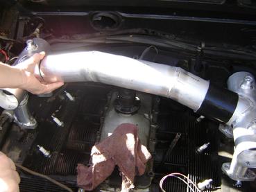
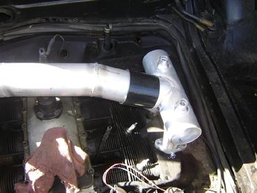
Crossover before fitting throttle body mount
More EFI manifold pics soon. Stay tuned.
02.07.2012
Here is the center section being fit. Silicone couplers will attach the section to each side assembly. The throttle body mount still needs to be finished and welded into the center section. The center is designed to provide clearance to the blower bearing. Enough space has been allowed for belt changes.
02.12.2012
Right side plenum with silicone coupler
Trial fitting crossover with silicone couplers
Here is the crossover held in place with the silicone couplers. The throttle body mount is about finished. I'll be fitting the mount to the crossover soon.
02.19.2012
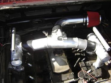
EFI trial with TB and filter attached
And now for the latest photos of my EFI system. Coming along nicely. The injectors are mounted on the plenums with the fuel rails sitting on top. I still need to tap the fuel rail ends for the AN fittings. And the end caps on the plenums need to be welded on. I will be adding a bung for a PCV valve and tapping the top right of the TB mount for the addition of a hose barbed fitting. This will supply vacuum to the fuel regulator and the MAP sensor.
The item on the top of the TB mount is the IAC (idle air control) valve. This supplies bypassed air for idle control.
03.03.2012
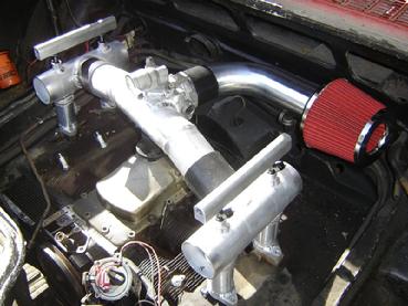
Right side view. Note injectors w/ fuel rails.
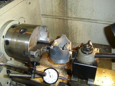
Piston secured, all zero's set, ready to cut
I finished machining the TRW .040" over pistons today for full floating pins. I'll be using double tru-arc locks set up w/ .005" end play on the pins. I have 4 more pins to turn down to the correct length. Once finished I'll be sending the pins off for DLC coating. Then have the stock rod's small ends honed for clearance.
I wanted to do this for ease of assembly and use the DLC coating for friction reduction.
I am finally getting close to short block trial assembly so I can check valve to piston clearances.
The heads just need a bit of high temp epoxy around each intake guide boss and some smoothing. Then they will be finished.
04.05.2012
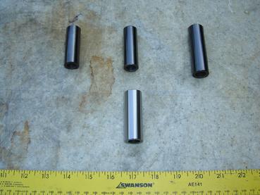
3 DLC coated pins and 1 non-coated
It's been a while since I last posted any updates.
I've been busy with customers engine work so my stuff has to sit and wait.
The pins have returned from the coating company. I had 3 sets DLC coated and you can see the difference at the left. From left to right, the first pin is a shortened pin for my used .040" OS TRW pistons I will use in the 65 Convertible. Same piston as shown in the photo above. Next is a pin for my custom made JE pistons that will run in my 3.0L. 3rd is a pin for the 92MM big bore pistons going in an engine for a fellow from Houston. Lastly, below these is a non-coated pin for the 92MM VW piston.The difference is plain to see.
The DLC coating has 2 main functions. At least for me. First it is extremely long wearing. Secondly it is very slippery. Both very good attributes. And it is an extremely thin coating; on the order of 3 microns. So no need to worry about machined surfaces varying in specifications.
I don't do any rod work in my shop so the local machine shop has rods and pins. They will hone the rod small ends to fit.
05.24.12
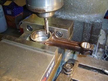
Rod for VW pin, cutting the slot for oil squirting
Here is a stock rod for a 92MM big bore engine I am building. The pin bore has been opened with a boring bar just shy of finished dimension. Small end will be honed to final size. An oil hold has been added to the top of the small end since this will be a full floating assembly. I have just cut the groove to allow oil from the rod bearing to sling out to the underside of the piston. 1 groove is cut on each side of the rod. This provides oil spray similar to the oil squirters Porsche added to their engines. Porsche found the oil spray reduced piston dome temps by up to 50 deg F.
Oh, on the picture above the pin on the right is for this big bore engine.
05.28.2012
DLC coated lifters, Sealed Power brand.
I have sent out the valve lifter bodies and rocker arm pivots to be DLC coated. These should come back in a couple of weeks. Then I'll be ready for the first trial assembly. I think I will set the pushrod lengths at this time. Pictures will be coming once the parts return.
07.29.2012
The lifter bodies returned along with the rocker pivot balls. The lifters are perfect but the pivots did not work out. Seems during manufacture one of the later steps is to oil quench the pivots during the heat treat process. The oil becomes impregnated into the metal. Well, the process for the DLC coating requires NO out gassing but the oil compromised that. So..., I'll use another set of pivots. Ya win some and ya lose some.